Week 13 - Overview
Learning Summary
1. Understanding Output Devices:
- Definition and importance of output devices in digital fabrication.
- LEDs: Light-emitting diodes for visual output.
- LCD and OLED Displays: Screens that display text and images.
- Motors: Includes DC, stepper, and servo motors for motion control.
- Other Actuators: Devices that move or control mechanisms or systems.
- How to integrate these devices with microcontrollers.
- Example projects and applications that utilize these output devices.
- Programming techniques for controlling devices dynamically.
- Use of various software tools and coding languages to manipulate output devices.
measure the power consumption of an output device
- add an output device to a microcontroller board you've designed,
and program it to do something
Reference Links
Week13 Output Devices Guide for my Fab Academy Journey.My personal assignment
1.Summarize the core knowledge points of Output Devices.
In this lesson, I learned about a variety of Output sensors, including analog and digital signal Outputs.
There are many types, involving the collection of various data, which is very interesting.
Here are some common output devices along with specific component models:
1. LEDs (Light Emitting Diodes):
- WS2812B: Individually addressable RGB LED.
- Cree XLamp CXA2011: High-power LED for lighting applications.
2. LCD Displays:
- HD44780: Standard 16x2 character LCD.
- ILI9341: 2.4" TFT LCD for graphical display.
3. OLED Displays:
- SSD1306: 0.96" OLED display.
- SH1106: 1.3" OLED display.
4. Speakers:
- MY9221: Miniature speaker for portable devices.
- Visaton BF37: Compact full-range speaker.
5. Buzzers:
- KY-012: Passive buzzer module.
- PS1240: Piezoelectric buzzer.
6. Motors:
- NEMA 17: Standard stepper motor.
- SG90: Micro servo motor.
- 775 DC Motor: High-torque DC motor.
7. Relays:
- SRD-05VDC-SL-C: 5V relay module.
- Omron G5Q: Compact power relay.
8. Heaters:
- MK2B: Heated bed for 3D printers.
- KSD9700: Temperature control switch for heating applications.
2.Tools、Software & Machine Introduction
Software:Kicad
KiCad is a free and open-source electronics design automation (EDA) suite.
It features schematic capture, integrated circuit simulation, printed circuit board (PCB) layout, 3D rendering, and plotting/data export to numerous formats.
KiCad also includes a high-quality component library featuring thousands of symbols, footprints, and 3D models.
KiCad has minimal system requirements and runs on Linux, Windows, and macOS.
Learn the various functions of KiCad.


Arduino IDE:
Arduino IDE (Integrated Development Environment) is an open-source software used for writing and uploading code to Arduino-compatible boards.
It provides an easy-to-use environment for both beginners and professionals to develop various electronic and robotic projects.
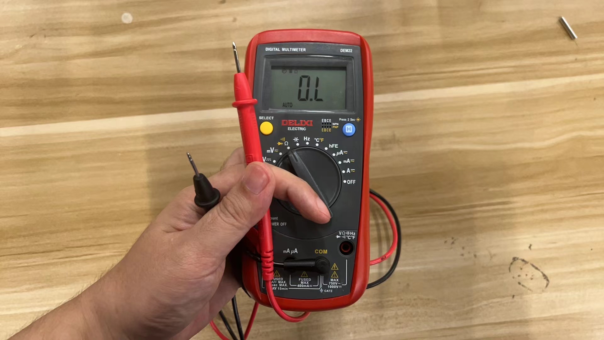
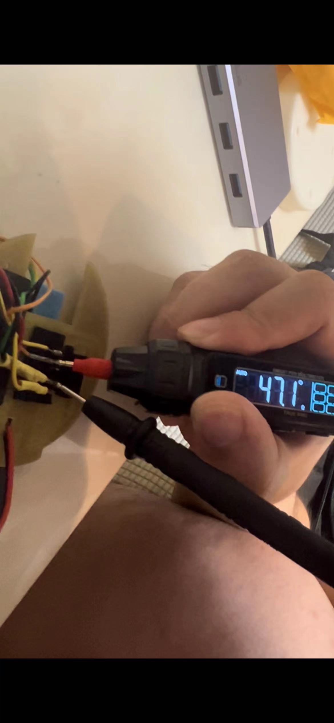
Multimeter Basic Steps to Use a Multimeter:
Select the Correct Mode: Depending on what you need to measure (voltage, current, resistance), set the dial on the multimeter to the correct function.
Connect the Probes: For most measurements, connect the black probe to the common terminal and the red probe to the appropriate terminal (voltage, ohm, or mA).
Measurement:
Voltage: To measure voltage, place the probes across the component or part of the circuit where you want to measure the voltage.
Current: To measure current, the circuit must be opened, and the multimeter must be placed in series with the circuit so that the current flows through the multimeter.
Resistance: To measure resistance, ensure the circuit power is off and place the probes across the component to measure its resistance.
Continuity: The multimeter will emit a tone if there is continuity (i.e., a complete path) between two points.
3.Output conmponents: NeoPixels(ws2812b)
The design process of NeoPixels:
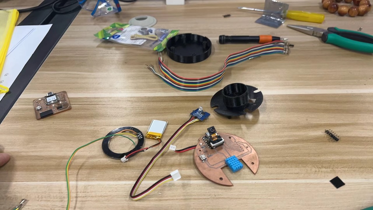
In designing the output involving the NeoPixel ring, I initially used my own PCB design. However, I encountered significant issues with trace routing because we used 12 NeoPixels, and each NeoPixel, according to the documentation, required the addition of a capacitor. This made it challenging to carve the PCB using CNC due to the limitations imposed by the trace width.
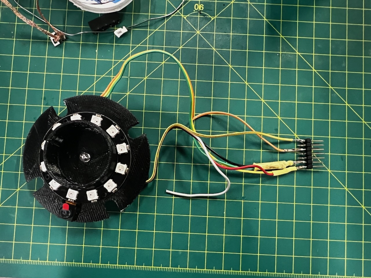
On the advice of my instructor Salman, he provided me with a pre-made 12 NeoPixel ring, allowing me to use a ready-made module to complete my output design.
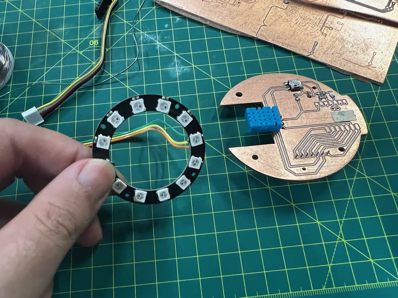
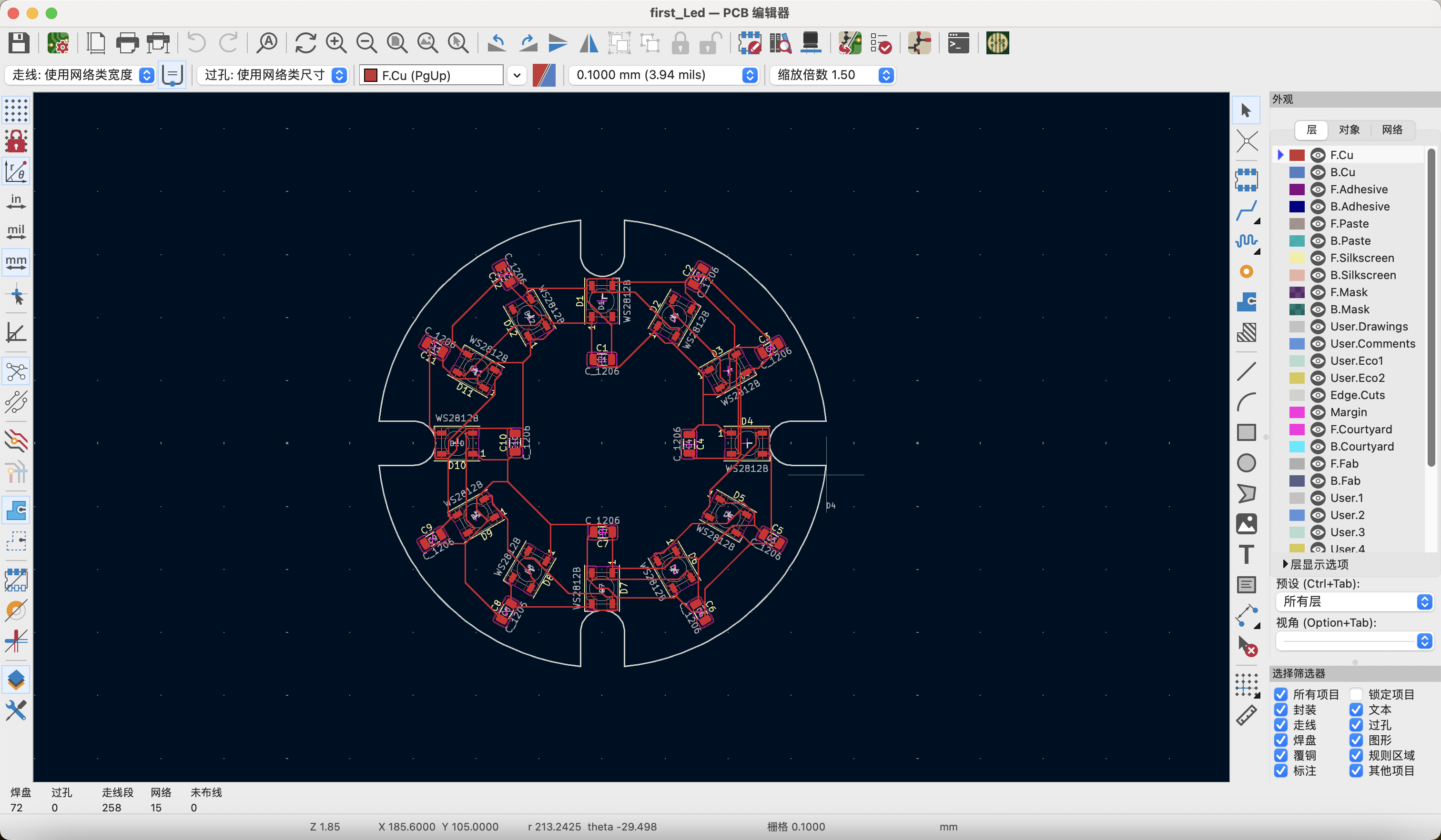
After using the new ring, I adjusted my design plan. The original plan was to design another PCB to accommodate 12 NeoPixels.
However, after switching to the 12 NeoPixel ring method, I redesigned the support structure to accommodate this component.
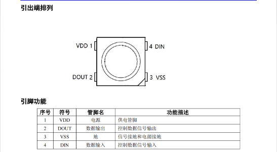
The WS2812B RGB LED
The WS2812B is an individually addressable RGB LED, often used in digital lighting and display applications.
Each LED contains an integrated control circuit and can be controlled independently, allowing for complex lighting patterns and color effects.
I chose the 12-pixel ring of WS2812B LEDs for my project.
Key Features:
- Integrated Controller: Each LED has its own integrated controller, allowing for independent control of color and brightness.
- 3-Pin Interface: Requires only three connections: VCC, GND, and Data In.
- Wide Color Range: Capable of producing 16 million colors.
- Daisy-Chainable: Multiple LEDs can be connected in series.
- Fast Refresh Rate: Suitable for animations and dynamic lighting.
Applications:
- LED strips for home decoration.
- Backlighting for displays.
- Wearable electronics.
- Custom digital displays and signage.
From the component library, locate the schematic symbols for the main components to be used: XiaoESP32-S3, DHT11.
We can learn the usage information of the sensor from the datasheet.
The Data Sheet for WS2812B:
4.Programming Process
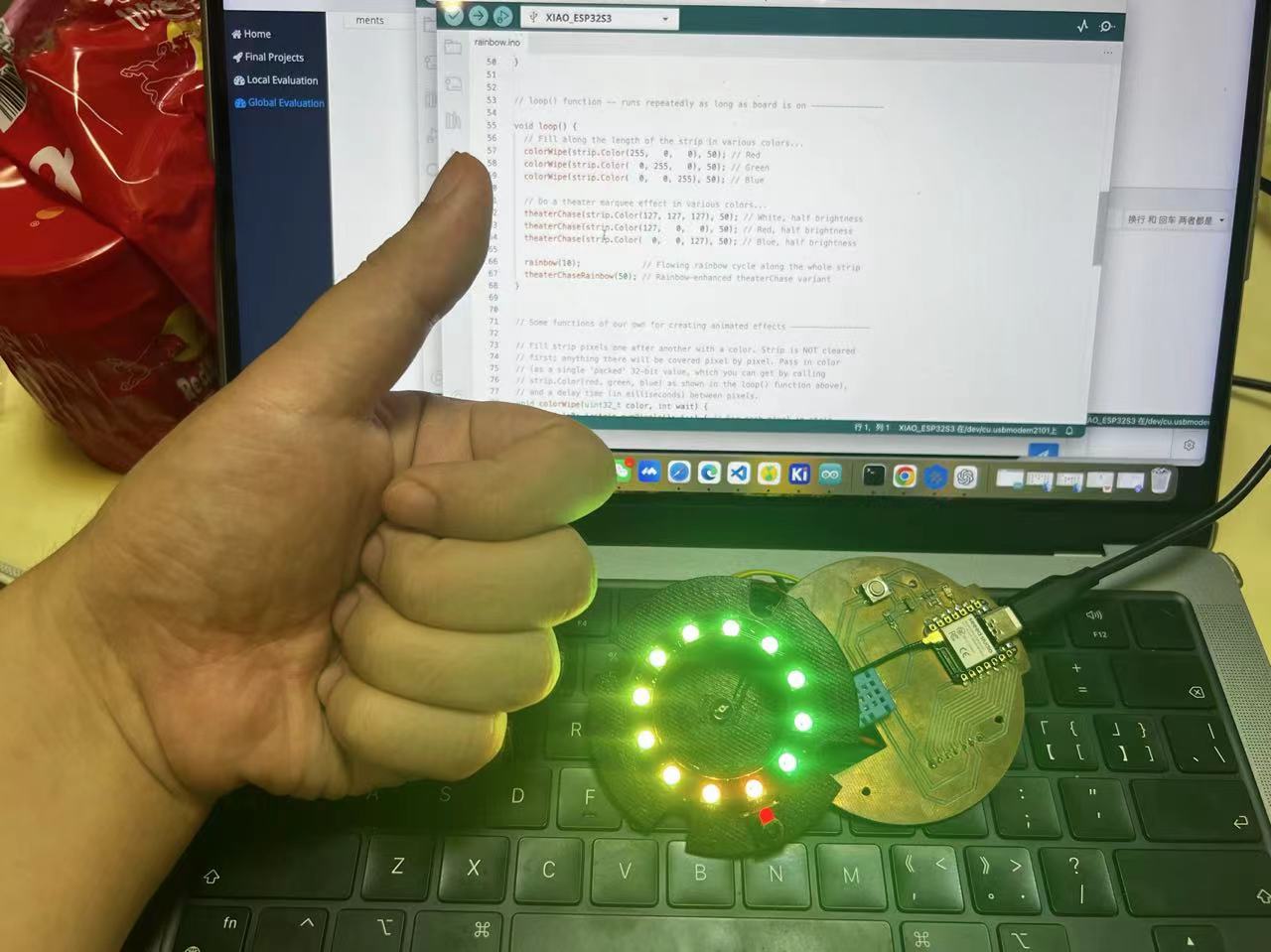
1. Hardware Connection
- I used the Dao clock Main board to test the 12-pixel ring of WS2812B,and I connected it to XiaoESP32-S3
- Connect the Dao clock Main board to the computer using a USB cable.
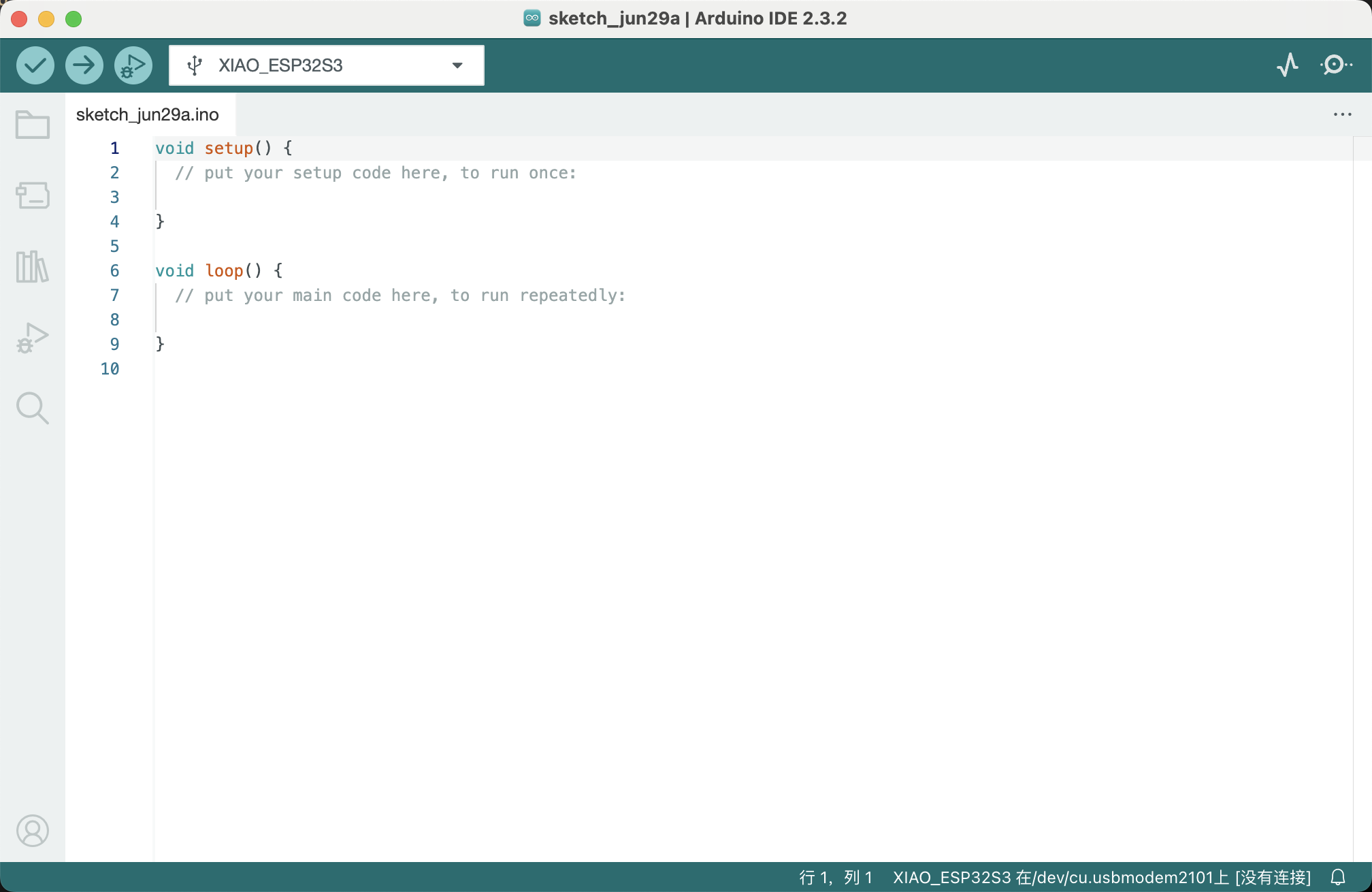
2. Software Configuration
- Open the Arduino IDE and select the board and port for the ESP32-S3.
- Select the correct COM port for the board.
- Use a test Demo program
- Setup The 12-pixel ring of WS2812B in the pin of D9
- Upload the program to the ESP32-S3 board.


3.My program requirements
First,I want the 12-pixel ring of WS2812B can be lit up in different colors.
It use for test the output effects of the NeoPixel.
Therefore, I am adding conditions for temperature and humidity.
I will print the real-time temperature and humidity values on the serial monitor.
Here is the code for my program:
#include
  #include "Grove_Temperature_And_Humidity_Sensor.h"
  #ifdef __AVR__
  #include   // Required for 16 MHz Adafruit Trinket
  #endif

  // Which pin on the Arduino is connected to the NeoPixels?
  #define PIN D9  // On Trinket or Gemma, suggest changing this to 1

  // How many NeoPixels are attached to the Arduino?
  #define LED_COUNT 12  // Popular NeoPixel ring size

  // When setting up the NeoPixel library, we tell it how many pixels,
  // and which pin to use to send signals. Note that for older NeoPixel
  // strips you might need to change the third parameter -- see the
  // strandtest example for more information on possible values.
  Adafruit_NeoPixel strip(LED_COUNT, PIN, NEO_GRB + NEO_KHZ800);

  #define DELAYVAL 500  // Time (in milliseconds) to pause between pixels

  #define DHTTYPE DHT11      // DHT 11
  #define DHTPIN D6          // what pin we're connected to(DHT10 and DHT20 don't need define it)
  DHT dht(DHTPIN, DHTTYPE);  //   DHT11 DHT21 DHT22
  #if defined(ARDUINO_ARCH_AVR)
  #define debug Serial

  #elif defined(ARDUINO_ARCH_SAMD) || defined(ARDUINO_ARCH_SAM)
  #define debug SerialUSB
  #else
  #define debug Serial
  #endif

  int sensorpin = A8;   // Analog input pin that the sensor is attached to
  int sensorValue = 0;  // value read from the port
  int outputValue = 0;  // value output to the PWM (analog out)


  void setup() {
    // These lines are specifically to support the Adafruit Trinket 5V 16 MHz.
    // Any other board, you can remove this part (but no harm leaving it):
  #if defined(__AVR_ATtiny85__) && (F_CPU == 16000000)
    clock_prescale_set(clock_div_1);
  #endif

    strip.begin();            // INITIALIZE NeoPixel strip object (REQUIRED)
    strip.show();             // Turn OFF all pixels ASAP
    strip.setBrightness(10);  // Set BRIGHTNESS to about 1/5 (max = 255)
    // END of Trinket-specific code.
    debug.begin(115200);
    debug.println("Light Humi & Temp test!");
    Wire.begin();
    pinMode(sensorpin, INPUT);
    Serial.begin(115200);
  }


  void loop() {
    // The first NeoPixel in a strand is #0, second is 1, all the way up
    // to the count of pixels minus one.
    // Fill along the length of the strip in various colors...
    colorWipe(strip.Color(255, 0, 0), 10);  // Red
    colorWipe(strip.Color(0, 255, 0), 10);  // Green
    colorWipe(strip.Color(0, 0, 255), 10);  // Blue

    // Do a theater marquee effect in various colors...
    theaterChase(strip.Color(127, 127, 127), 10);  // White, half brightness
    theaterChase(strip.Color(127, 0, 0), 10);      // Red, half brightness
    theaterChase(strip.Color(0, 0, 127), 10);      // Blue, half brightness

    rainbow(10);              // Flowing rainbow cycle along the whole strip
    theaterChaseRainbow(50);  // Rainbow-enhanced theaterChase variant

    sensorValue = analogRead(sensorpin);
    debug.print("Light Parameter: ");
    debug.print(sensorValue);
    debug.print("\t");

    float temp_hum_val[2] = { 0 };
    // Reading temperature or humidity takes about 250 milliseconds!
    // Sensor readings may also be up to 2 seconds 'old' (its a very slow sensor)
    if (!dht.readTempAndHumidity(temp_hum_val)) {
      debug.print("Humidity: ");
      debug.print(temp_hum_val[0]);
      debug.print(" %\t");
      debug.print("Temperature: ");
      debug.print(temp_hum_val[1]);
      debug.println(" *C");
    } else {
      debug.println("Failed to get temprature and humidity value.");
    }
    delay(200);
  }

  void colorWipe(uint32_t color, int wait) {
    for (int i = 0; i < strip.numPixels(); i++) {  // For each pixel in strip...
      strip.setPixelColor(i, color);               //  Set pixel's color (in RAM)
      strip.show();                                //  Update strip to match
      delay(wait);                                 //  Pause for a moment
    }
  }

  // Theater-marquee-style chasing lights. Pass in a color (32-bit value,
  // a la strip.Color(r,g,b) as mentioned above), and a delay time (in ms)
  // between frames.
  void theaterChase(uint32_t color, int wait) {
    for (int a = 0; a < 10; a++) {   // Repeat 10 times...
      for (int b = 0; b < 3; b++) {  //  'b' counts from 0 to 2...
        strip.clear();               //   Set all pixels in RAM to 0 (off)
        // 'c' counts up from 'b' to end of strip in steps of 3...
        for (int c = b; c < strip.numPixels(); c += 3) {
          strip.setPixelColor(c, color);  // Set pixel 'c' to value 'color'
        }
        strip.show();  // Update strip with new contents
        delay(wait);   // Pause for a moment
      }
    }
  }

  // Rainbow cycle along whole strip. Pass delay time (in ms) between frames.
  void rainbow(int wait) {
    // Hue of first pixel runs 5 complete loops through the color wheel.
    // Color wheel has a range of 65536 but it's OK if we roll over, so
    // just count from 0 to 5*65536. Adding 256 to firstPixelHue each time
    // means we'll make 5*65536/256 = 1280 passes through this loop:
    for (long firstPixelHue = 0; firstPixelHue < 5 * 65536; firstPixelHue += 256) {
      // strip.rainbow() can take a single argument (first pixel hue) or
      // optionally a few extras: number of rainbow repetitions (default 1),
      // saturation and value (brightness) (both 0-255, similar to the
      // ColorHSV() function, default 255), and a true/false flag for whether
      // to apply gamma correction to provide 'truer' colors (default true).
      strip.rainbow(firstPixelHue);
      // Above line is equivalent to:
      // strip.rainbow(firstPixelHue, 1, 255, 255, true);
      strip.show();  // Update strip with new contents
      delay(wait);   // Pause for a moment
    }
  }

  // Rainbow-enhanced theater marquee. Pass delay time (in ms) between frames.
  void theaterChaseRainbow(int wait) {
    int firstPixelHue = 0;           // First pixel starts at red (hue 0)
    for (int a = 0; a < 30; a++) {   // Repeat 30 times...
      for (int b = 0; b < 3; b++) {  //  'b' counts from 0 to 2...
        strip.clear();               //   Set all pixels in RAM to 0 (off)
        // 'c' counts up from 'b' to end of strip in increments of 3...
        for (int c = b; c < strip.numPixels(); c += 3) {
          // hue of pixel 'c' is offset by an amount to make one full
          // revolution of the color wheel (range 65536) along the length
          // of the strip (strip.numPixels() steps):
          int hue = firstPixelHue + c * 65536L / strip.numPixels();
          uint32_t color = strip.gamma32(strip.ColorHSV(hue));  // hue -> RGB
          strip.setPixelColor(c, color);                        // Set pixel 'c' to value 'color'
        }
        strip.show();                 // Update strip with new contents
        delay(wait);                  // Pause for a moment
        firstPixelHue += 65536 / 90;  // One cycle of color wheel over 90 frames
      }
    }
  }
5.Some Problems and Solutions.
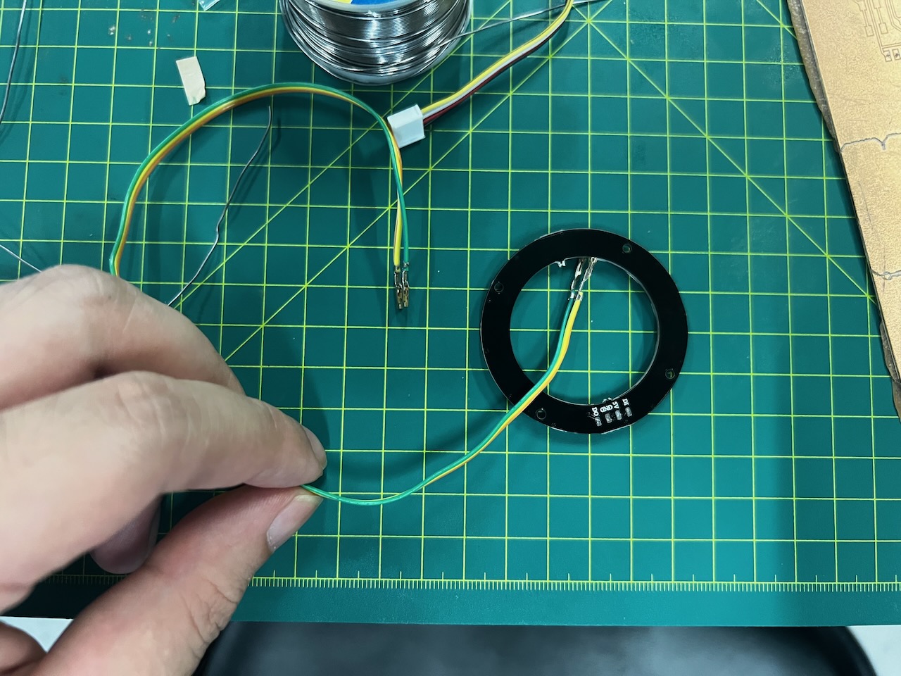
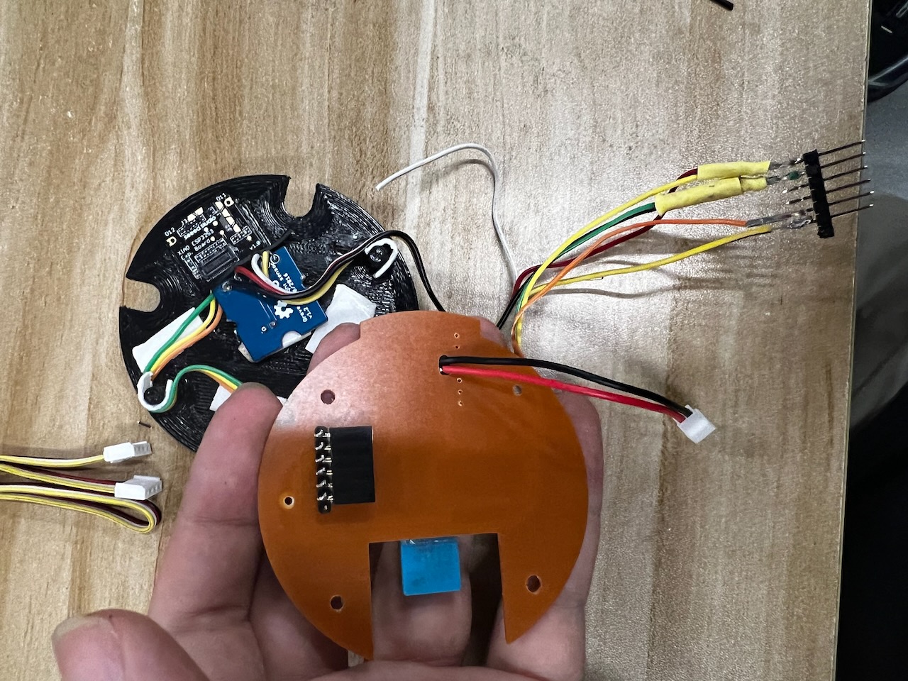
Due to the very small soldering points on the ring, I used jumpers and pin components, which easily led to loose connections and broken wires.
To fix this issue, I had to re-solder three times, and finally ensured its stability.
This was a significant exercise and improvement for my soldering skills.
6.The Hero Shots
Team Assignment
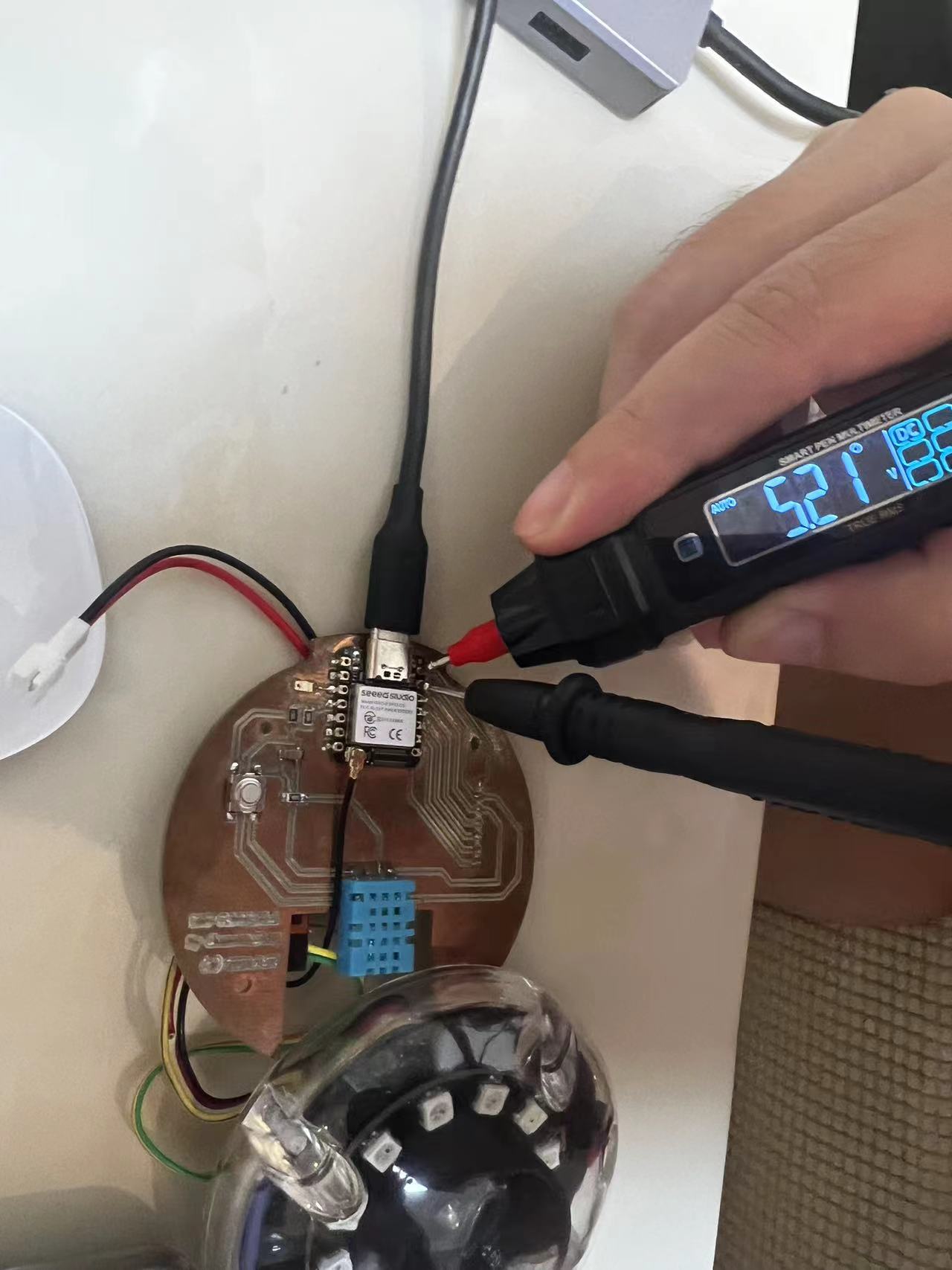
To calculate the power consumption of the ring of 12 NeoPixel lights, we first need to calculate the current through the resistor using Ohm's law, and then use the power formula \( P = V \times I \) to calculate the power consumption.
First, according to Ohm's law \( V = I \times R \), we can find the current \( I \):
- \( I = \frac{V}{R} \)
- Where \( V \) is the voltage, and \( R \) is the resistance.
- The given voltage \( V \) is 5.21 volts, and the resistance \( R \) is 47.1 ohms.
- \( I = \frac{5.21 \text{ volts}}{47.1 \text{ ohms}} \approx 0.1106 \text{ amperes} \)
Now that we have the current, we can calculate the power \( P \):
- \( P = V \times I = 5.21 \text{ volts} \times 0.1106 \text{ amperes} \approx 0.576 \text{ watts} \)
Therefore, the power consumption of the ring of 12 NeoPixel lights is approximately 0.576 watts.
Let's Jump to the Top !!!